Solder paste

Results: 151


#Item
11S OL D ER PAS T E S C 150 Type ISOC The solder paste SOLDER CHEMISTRY SC 150 is the latest, unique creation specifically suitable for soldering in vapor phase and under inert gas. Not only many years of experience

S OL D ER PAS T E S C 150 Type ISOC The solder paste SOLDER CHEMISTRY SC 150 is the latest, unique creation specifically suitable for soldering in vapor phase and under inert gas. Not only many years of experience

Add to Reading List

Source URL: www.solderchemistry.com

Language: English - Date: 2007-12-17 08:34:27
12www.EPOTEK.com  Epoxy Adhesive Application Guide  This guide is an educational tool designed to assist adhesive users in

www.EPOTEK.com Epoxy Adhesive Application Guide This guide is an educational tool designed to assist adhesive users in

Add to Reading List

Source URL: www.epotek.com

Language: English - Date: 2016-03-22 09:00:37
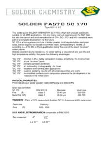
13S OL D ER PAS T E S C 170 Type ISOC The solder paste SOLDER CHEMISTRY SC 170 is a high tech product specifically suitable for all SMT applications. Not only many years of experience in the SMT field, but also the

S OL D ER PAS T E S C 170 Type ISOC The solder paste SOLDER CHEMISTRY SC 170 is a high tech product specifically suitable for all SMT applications. Not only many years of experience in the SMT field, but also the

Add to Reading List

Source URL: www.solderchemistry.com

Language: English - Date: 2007-12-17 08:34:32
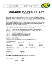
14S OL D ER PAS T E S C 127 Type ISOC The solder paste SOLDER CHEMISTRY SC 127 is a high tech product especially suitable for all SMT applications. Not only many years of experience in the SMT field, but also the ca

S OL D ER PAS T E S C 127 Type ISOC The solder paste SOLDER CHEMISTRY SC 127 is a high tech product especially suitable for all SMT applications. Not only many years of experience in the SMT field, but also the ca

Add to Reading List

Source URL: www.solderchemistry.com

Language: English - Date: 2007-12-17 08:34:25
15SOL205B  Patent Pending Back-side PastE

SOL205B Patent Pending Back-side PastE

Add to Reading List

Source URL: www.heraeus.com

Language: English - Date: 2016-08-12 05:25:57
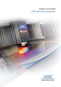
16Always a Cut Ahead LPKF StencilLaser Equipment Commitment and Innovation LPKF has been introducing innovations in electronics manufacturing for more than 30 years. The LPKF StencilLaser established a new form of electro

Always a Cut Ahead LPKF StencilLaser Equipment Commitment and Innovation LPKF has been introducing innovations in electronics manufacturing for more than 30 years. The LPKF StencilLaser established a new form of electro

Add to Reading List

Source URL: www.lpkf.com

Language: English - Date: 2013-08-26 05:44:37
17The Most Efficient SMT Solder Paste Stencil Cutter Available LPKF StencilLaser G 6080 • Improved Quality • No Chiller Needed • In Process Inspection

The Most Efficient SMT Solder Paste Stencil Cutter Available LPKF StencilLaser G 6080 • Improved Quality • No Chiller Needed • In Process Inspection

Add to Reading List

Source URL: www.lpkf.fr

Language: English - Date: 2015-08-21 07:34:25
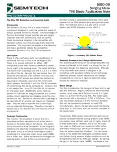
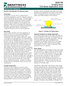
    18SI00-06  Surging Ideas TVS Diode Application Note PROTECTION PRODUCTS Semtech utilizes a proprietary electroless nickel plate

    SI00-06 Surging Ideas TVS Diode Application Note PROTECTION PRODUCTS Semtech utilizes a proprietary electroless nickel plate

    Add to Reading List

    Source URL: www.semtech.com

    Language: English - Date: 2013-04-03 13:11:08
    19SI00-06  Surging Ideas TVS Diode Application Note PROTECTION PRODUCTS Semtech utilizes a proprietary electroless nickel plate

    SI00-06 Surging Ideas TVS Diode Application Note PROTECTION PRODUCTS Semtech utilizes a proprietary electroless nickel plate

    Add to Reading List

    Source URL: www.semtech.com

    Language: English - Date: 2013-04-03 13:11:08
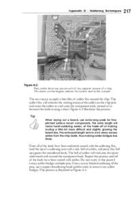
    20Appendix B - Soldering Techniques  Figure A-2: First, solder down one pin on each of two opposite corners of a chip. The arrows on this diagram indicate the corners used in this example.

    Appendix B - Soldering Techniques Figure A-2: First, solder down one pin on each of two opposite corners of a chip. The arrows on this diagram indicate the corners used in this example.

    Add to Reading List

    Source URL: www.xenatera.com

    Language: English - Date: 2003-04-17 05:00:01